Fireproof compartmentalisation
INTRODUCTION
To prevent and fight fire, it is necessary to know its causes and conditions. In this and the following paragraphs, we highlight a fire's basic elements and any applicable
measures so:
- the fire doesn't break out;
- the fire won't spread;
- people are quickly rescued;
- flames and gas can be quickly extinguished.
This knowledge allows a better understanding of the difference between prevention, passive and active protection, and structural protection and compartmentalisation which are the two macro areas of passive fire protection.
The last part of the introduction details the compartmentalisation of areas which have discontinuities along their perimeter, with a focus on mechanical, electrical system penetrations, and expansion joints.
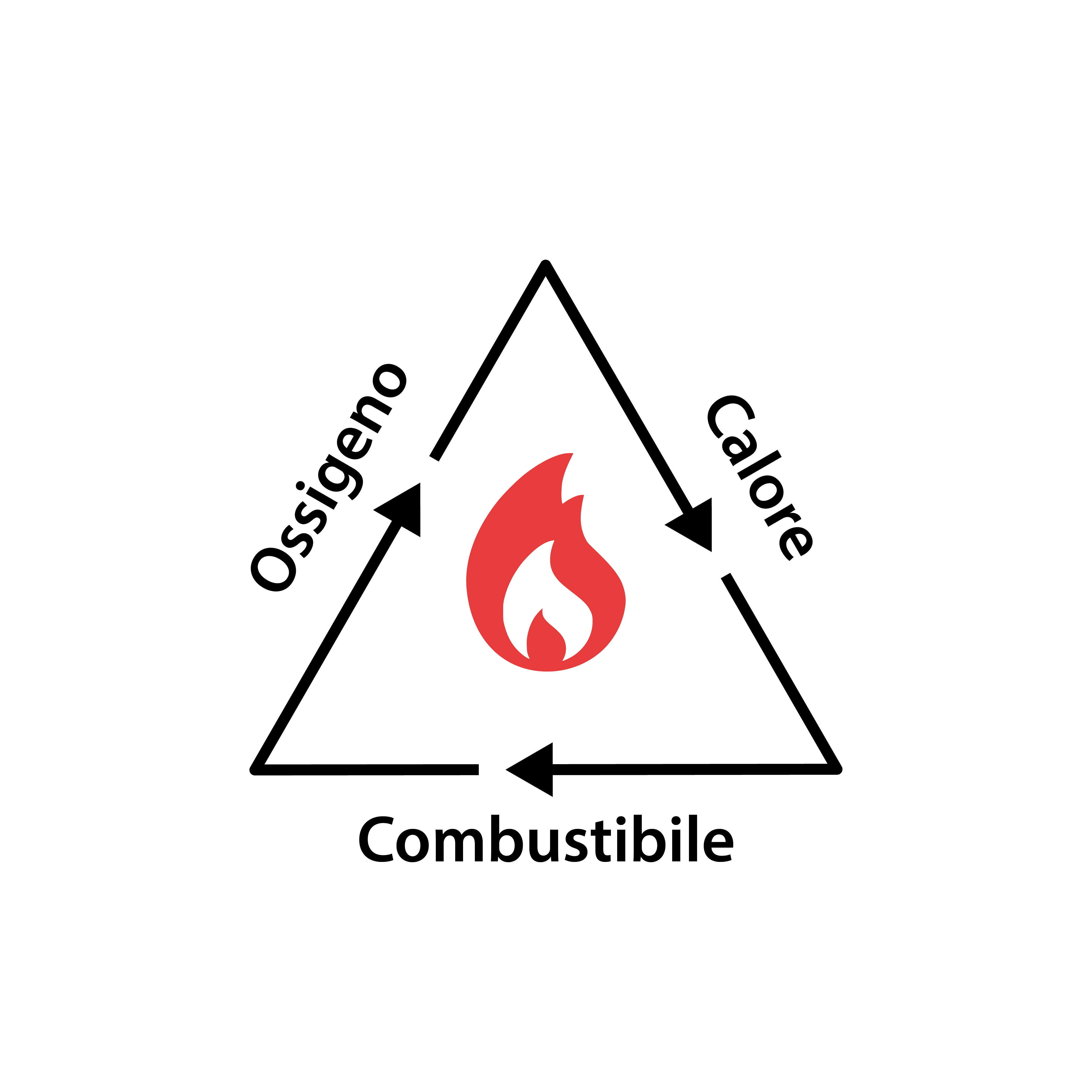
Fire is the "uncontrolled" combustion of solids, liquids or gases in an unprepared place, or at an unexpected time, due to thermal, mechanical, electrical or human ignition. Technically, fire is an exothermic oxidation-reduction reaction in which a "fuel" (1) is oxidised and an "oxidiser" (2) is reduced, via a source of ignition (3).
(1) Fuels are substances which react with oxygen (or another oxidiser). They can be classified according to their physical state, differentiating into solid, liquid and gaseous fuels, and produce thermal energy following a combustion reaction. A fundamental feature of each fuel is its calorific value, i.e. the maximum energy that can be obtained from the complete combustion of a unit of fuel under standard conditions.
Each material has a temperature above which it continues to burn and below which it tends to burn out -
the ignition temperature
.
(2) Oxidisers are substances capable of oxidising combustible materials, the most common being oxygen contained in the air. Other liquid, solid or gaseous oxidising substances, which permit combustion, are potassium nitrate, potassium permanganate, hydrogen peroxide, potassium chromate and nitrous oxide.
(3) Ignition sources are heat sources which raise the fuel temperature during combustion.
They are divided into: friction, direct and indirect ignition.
Friction ignition is when heat is produced by rubbing two materials.
Direct ignition is when a flame, spark or other incandescent material comes into contact with a combustible material in the presence of oxygen.
Indirect ignition is when the ignition heat is transmitted by convection (when the transmission of heat is accompanied by a movement of matter), conduction (when heat propagates through solid elements) or radiation (when the energy is propagated directly in the form of electromagnetic waves).
Figure 1 | The "triangle" of fire
Each fire has four phases: ignition and initial spread, flashover, generalised fire and decay.
1 - Ignition
during this phase, the combustion process begins due to the effect of a thermal source that heats the fuel until it reaches its ignition temperature.
The propagation of this phenomenon requires the three elements described in the previous paragraph and shown below as the sides of a hypothetical fire "triangle" (
Figure 1
). Without one of the factors, ignition, and fire, cannot occur.
Breaking the fire triangle results in the fire being extinguished. This operation can be carried out on each of the three sides, depending on the component involved: separation (if the fuel is removed from the fire), suffocation (if contact between the air or oxygen and the fuel is prevented), cooling (if the temperature below the ignition temperature of the substances is lowered).
During this phase, if the burning combustible object is far from other combustible material, the fire cannot spread and, once the fuel is exhausted, combustion ceases. If the burning fuel comes into contact with other combustible material, due to the effect of pyrolysis, easily ignitable vapours and gases can be generated. The fire spreads to the various combustible elements and then, gradually, to the whole room.
2 - Flashover
During this phase, also called "flashover point", the combustion speed increases, the temperature rises and significant volumes of smoke and gases are produced with sudden flame propagation through unburned gases and vapours. This is a transitional stage from a growing to a fully developed fire where all combustible materials are simultaneously involved. Generally this phase involves an increase in temperature up to 500/600° in a short time (from 5-25 min).
3 - Generalised fire
Above flashover temperatures, most common materials are flammable and combustive. The transmission of heat within buildings becomes significant and the structural strength of walls, ceilings, columns and beams can be seriously compromised. The risk of deterioration and collapse of the load-bearing structures and the rapidity of fire spread, make this phase dangerous.
4 - Decay
The progressive exhaustion of the fuel starts a process of extinction with gradual reduction of the generated heat flow - this is the decay phase. During this phase, the cooling is slow and equally dangerous: apparently
cold zones may conceal latent fire waiting for "new fuel" to reignite. This phase conventionally ends when the temperature falls below 300°C.
"Fire Prevention", in the broadest sense, is the discipline that studies and implements all measures aimed at preventing, reporting and reducing the likelihood of occurrence of a fire and limit the consequences for people, property, production and the environment.
Prevention includes fire protection measures, and training activities on risks and behaviour when planning a fire-fighting strategy.
To reduce the fire risk to a minimum, it is necessary to have adequate knowledge of the risks connected to the use of certain materials (e.g. specific calorific value), if it is possible to physically separate environments with a high fire risk (such as any room relocation in the design phase), standards and systems available to achieve a degree of protection.
"
Fire protection
" is based on a set of measures to reduce the risks and damage caused by a fire outbreak (damage to persons, structures, activities and the environment) by acting on the fire's magnitude (Risk = Frequency x Magnitude).
This is a general definition and applies to any type of activity or construction: a building, industry, tunnel (road or rail) or a materials depot.
It is important to properly balance prevention, active and passive protection measures to mitigate the fire risk and safeguard life, property and the environment.
One of the most important objectives of passive fire protection is to ensure that structures can resist for a sufficient time to ensure the escape of all occupants and any fire extinguishing action by rescue teams or automated systems.
If there is a fire, this is jeopardised by high temperatures that alter the mechanical properties (strength and stiffness) of the load-bearing structures and decrease their ability to bear loads compared to ordinary operating conditions. To evaluate a load-bearing structure resistance rating, the European standard uses the variable "R" (stability) followed by a number indicating the time expressed in minutes the structure ability to withstand loads in normalised fire conditions (assessed under the ISO 834 fire curve). A wall or pillar with "R90" performance, for example, is certified to exert its load-bearing capacity for at least 90 minutes of fire. In addition to preventing structural collapse, passive protection measures prevent the fire from spreading beyond its place of origin. This risk is amplified in buildings with occupants with reduced mobility or high buildings where there is often only one "escape route" from the upper floors which must be kept free of flames, smoke and combustion gases. To deal with the risk of fire propagation, regulations require compartmentalising buildings, i.e. smaller areas, whose perimeter must guarantee "sufficient thermal insulation and seal against smoke and hot gases from combustion."
For partition and structural elements (e.g. walls and floors), in addition to the variable R, there are variables "E" for integrity/tightness to flames and hot gases and "I" for thermal insulation (
Table 1
).
Integrity is only possible if the structure remains intact during the test. Any cracking or failure in the structure would compromise infiltration and barrier thermal insulation. During testing, the control is carried out visually using a cotton ball that is placed on the most critical point (e.g. the protruding part of a combustible pipeline in the penetration). The ignition and permanence of the flame on the cotton determines the end of the test, even without evident collapses in the supporting structure.
Thermal insulation is measured by applying thermocouples at certain critical points of the sample established by the test standards. To pass the test, the temperature measured on the "unexposed" side must be maximum 140°C above the ambient temperature on average and none of the thermocouples must measure a difference of more than 180°C.
Stability, integrity and insulation requirements are indicated by the acronym "REI" which, followed by the minutes of fire resistance, represents the fire resistance performance of load-bearing separating elements.
Structural protection
We can distinguish three types of structures for passive protection objectives classification purposes:
-
Simple structures
Non-continuous elements (e.g. beams, pillars, tie rods, chains), with a purely mechanical support function. The lack of a partition role makes it possible to identify the fire-fighting function of these structures only through their "R" stability. To measure this requirement correctly, the tests must include loads representative of the actual weights that these elements will have to bear. For suspended elements (e.g. a tie rod) we suggest that the protective elements used are independently supported or relatively "light" to contain fire overheating without over-burdening the element.
-
Load-bearing vertical separating structures
Load-bearing walls typically made of masonry, reinforced cement and concrete, and rarely, in wood and composite or mixed panels.
-
Horizontal separating elements
Floors and roofing elements in addition to being separating elements must support other types of loads such as furniture, people and machinery, which can potentially move and vary in concentration in space during the building’s useful life. In addition to these loads, outdoor exposure may add additional stresses caused by atmospheric agents (snow and wind) or other specific loads (e.g. telecommunications antennas, transport vehicles, etc.). Due to these factors, any endurance test must be performed using technical evaluations that take these elements into account.
For all the structures above, higher thicknesses and densities provide better performance. The applicability of test results performed on structures with a given density and thickness values are automatically applied to the same type of structures with higher values of these parameters. To improve the mechanical strength requirements of these structures, plaster, intumescent paints or plasterboard/silicate lime coatings can be applied. These reduce the passage of heat, increase the insulation and the R and REI performance of the load-bearing or separating element.
Compartmentalisation
If there is a fire, it is essential to prevent the spread of flames to the entire building. The compartment identifies the area where the fire must be contained; if no compartmentalisation is provided, or if it is unnecessary, the building is the compartment.
The horizontal and vertical separating elements that define the compartment perimeter must guarantee a
smoke-proof
performance for a certain time (indicated with the letter "E") and
thermal insulation
(indicated with the letter "I"). To make sure they meet these requirements, walls and floors similar to those used in construction must have passed fire resistance tests under European standards EN 1364 and EN 1365 and have obtained a classification on these two properties better than or equal to that required for the elements used in the project. Alternatively, these elements must comply with the tabular features of Ministerial Decree of 16 February 2007 (Annex "D").
If there are wall and door (doors, shutters, installation penetrations or linear joints) discontinuities that reduce the insulating thickness or change the nature of materials which guarantee integrity and thermal insulation, the certificates obtained on the simple separation elements are insufficient. It is necessary that the installation is supported by certificates made on elements that are similar to those used on the building site.
Each element used to restore integrity and thermal insulation consistency acts differently depending on the discontinuity and must be applied following the installation instructions given in the manufacturer's sheets.. The work is not disconnected from the structure's construction, but must be seen as a whole and carried out with all the precautions and any complementary products used in the test. The suitability of a fireproof door or glass is not certified without testing the structure where the elements are inserted and any accessory products used to ensure a perfect seal. This discontinuity analysis emphasises the importance of the installation methods and leads to the preferential use of fireproof "systems" rather than fireproof products.
The main systems used to create a fire compartmentalisation on structures with discontinuities are listed below.
Let us begin this brief overview on technical closures and seals by talking about fire-resistant doors, commonly known as "REI doors." This type of closure is regulated by product standards. Since November 2019, after the coexistence period of the harmonised standard, the CE marking has become mandatory. At the time of writing, only external pedestrian or driveway doors (EN 14351-1) needed CE marking, while internal pedestrian doors (EN 14351-2) still required national type approval; each Member State has its own rules. Regardless of certification developments, smoke tightness has been introduced for industrial doors and gates, in addition to test procedure modifications. During the test, the smoke tightness measurements are carried out at room temperature (20°C) for Sa type doors, and at an intermediate temperature (double measurement, at 20°C and 200°C) for Sm type doors. The classification can be type "E", "EI" and "EW" (no longer "REI"), with the suffixes "-Sa" or "-Sm". Fire doors are subject to wear and tear or malfunction and should be serviced every six months .
Service installation penetrations
Due to technical installation penetrations type and number they are the biggest threat to compartmentalisation measures. This is a broad category, but it has some common elements. Each penetration redevelopment has three factors:
- pass-through services;
- support structure;
- products used.
To evaluate (and compare) different solutions it is necessary to consider each of these three factors. Certification of the fire resistance sealants installed by a fire-fighting professional must be based on
classification reports
or
technical approval (ETA)
that include the worksite case in their direct field of application (or extended under EXAP regulations).
No extension or evaluation is allowed even by a technician qualified and registered with the Ministry of the Interior. This challenges fireproof sealing system manufacturers because any major change affecting pass-through services, support structures or products needs a dedicated test, increasing the number of certifications required to cover an application area.
There is a single basic criterion that is implemented by all standards that regulate the installation penetrations (EN 1366) to extend test results: the results obtained in worst case scenarios can be considered valid and extended to penetrations that have similar or improved integrity and thermal insulation ability. For example, the certificate of a collar tested on a 120 mm thick plasterboard wall will be extendable to an application on a 150 mm thick concrete wall, but not the other way around. This requires manufacturers to test their systems in the most severe situations to extend the field of application of their solutions. Let's see below how this criterion applies for each of the three elements that define a penetration.
The installation type and configuration of elements crossing walls and floors is the first difference between penetrations. Recognising the "type" or nature of a service is straightforward: a cable is different from a pipe and a small diameter combustible pipe is different from a large metal pipe. The type of the pass-through element is crucial, in the following paragraphs we will use this criterion to subdivide each penetration feature.
The service installation configuration, which is the set of all construction, details certifying the penetration in the test phase, must be considered. These conditions are an integral part of a solution that is not always easy to replicate or verify outside specialised laboratories. Test configuration variations are possible if the element tested in the laboratory has a more severe fire behaviour set-up than real life. This happens when there are structures and related thickness around the penetration that increase the structure thickness and sealant depth.
A
practical example
is the perimeter of an opening delimited by a frame. If a frame was used in the test report to house and install the sealant, it must be constructed on site. Often he construction of additional structures is omitted for practical reasons or to save money.
The standard for fire resistance tests of service penetrations (EN 1366-3) does not allow this option because the system would have been laboratory tested in less severe conditions (using a frame) without any guarantee that it works without these structures. This means that most systems available on the market can use only the framed version (see image below). If the test used an opening sealed with fire sealant without any additional construction as in Figure 3a (worst case scenario), the sealing products can be applied in both configurations, i.e. with or without a frame (see Figures 3b and 3c).
It is important that there are no difficult installation configurations in the test phase to ensure the installed systems match what has been certified. AF Systems' R&D recent efforts have gone in this direction. It is important that the fire-fighting technician, who cannot extend or validate an installation system modification, analyses the solution in depth, according to certification limits.
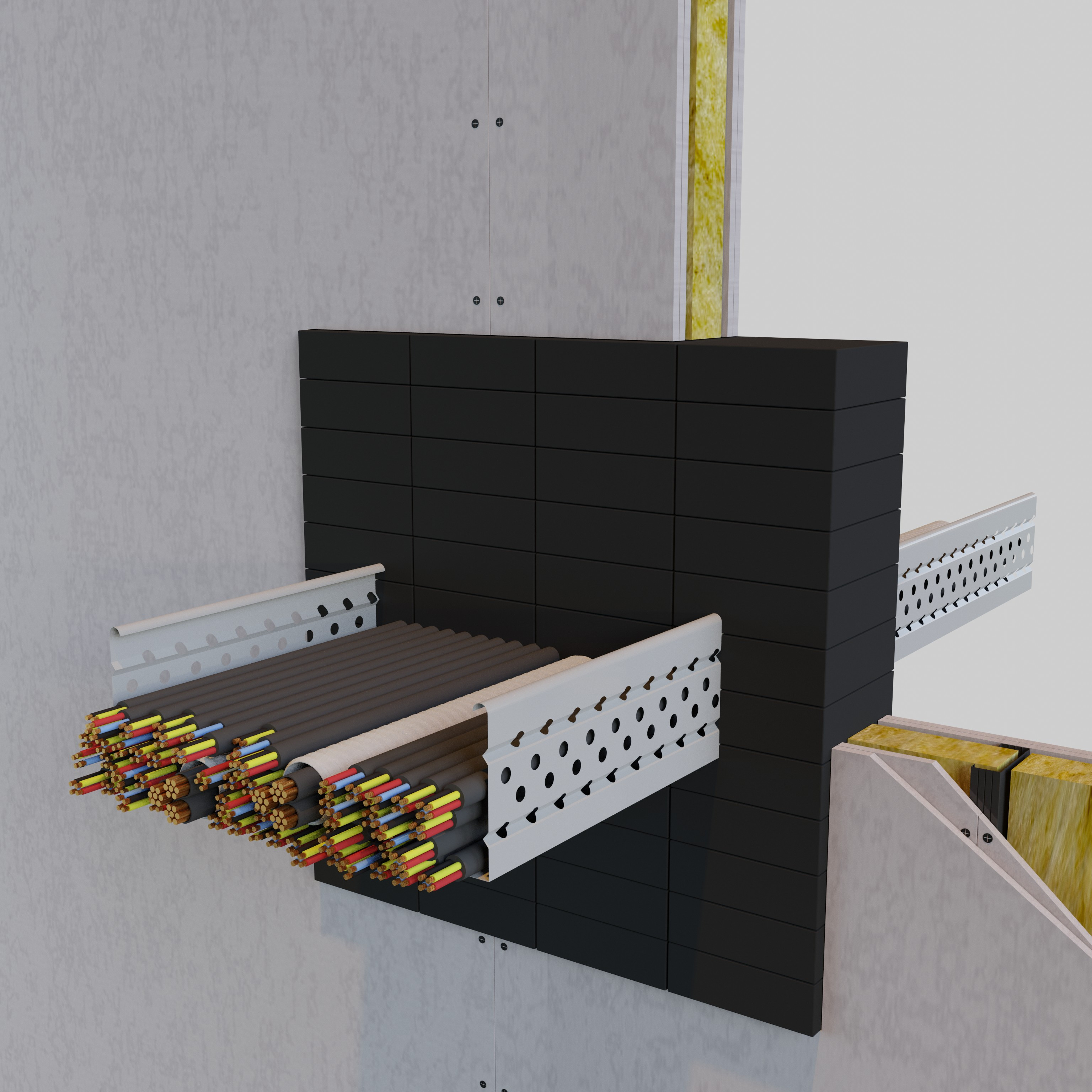 Figure 3a
AF Systems frameless solution
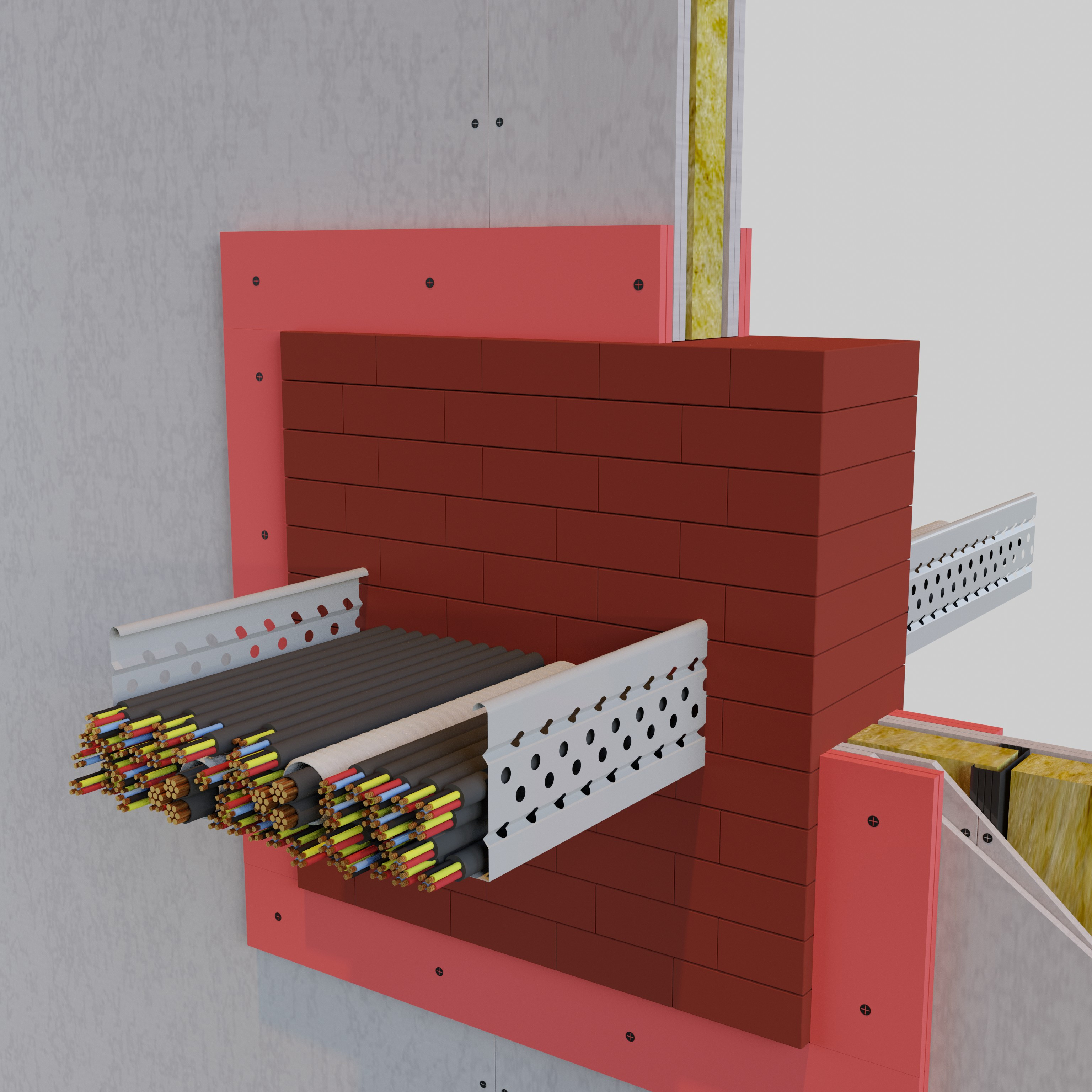 Figure 3b
Solution with external frame
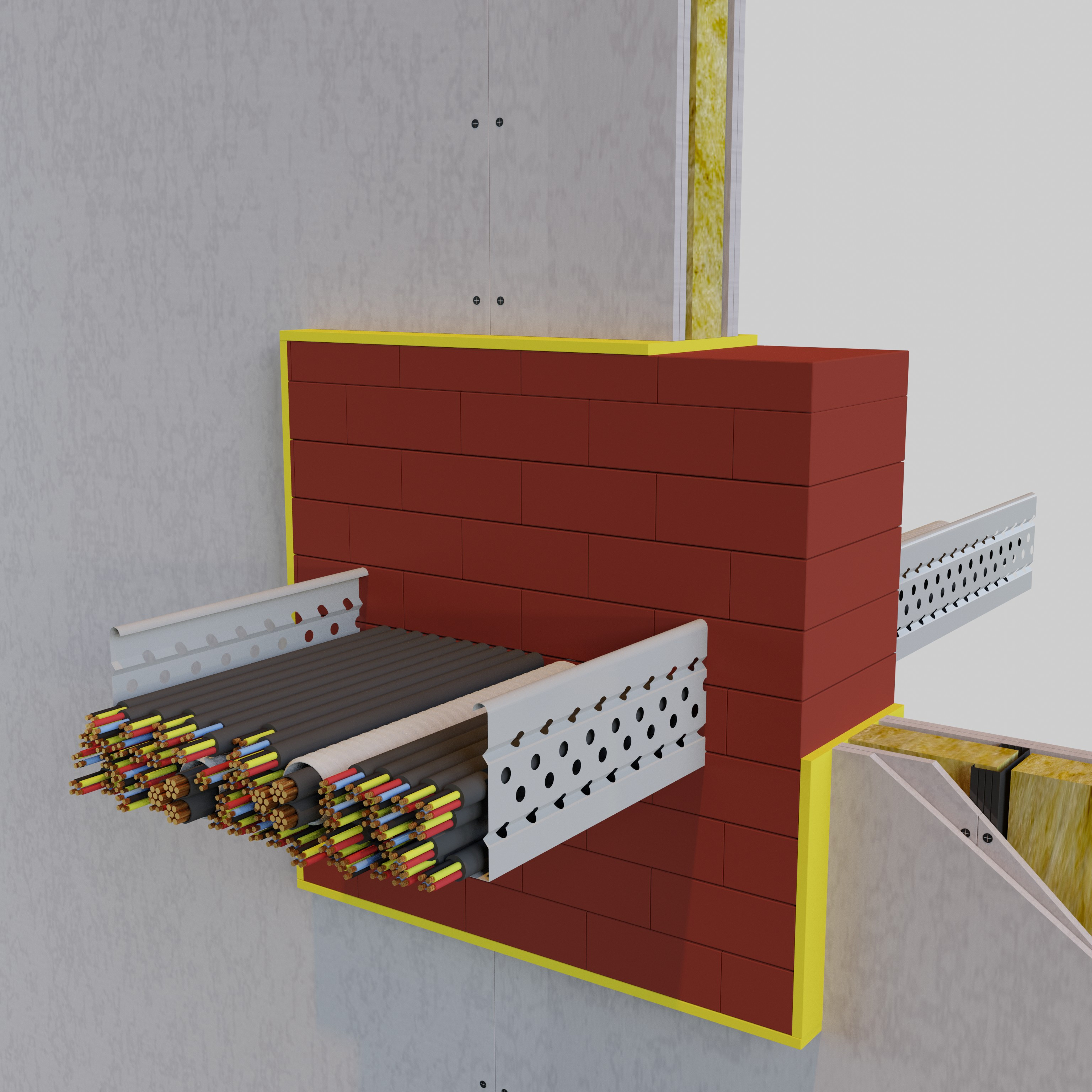 Figure 3c
Solution with internal frame
Support structure
The standard distinguishes between two types of support structures: flexible wall/floor (drywall or timber construction) and rigid wall/floor (masonry, concrete...). It is impossible to extend the results obtained on a horizontal support to a vertical support and vice versa. To comply with the certificate, the real structure must have a thickness and density greater than, or equal to, those tested. During the test, manufacturers use walls (or floors) of the lowest possible thickness and density, to ensure maximum result extendibility.
The standard allows the results obtained on a flexible structure to be extended to a rigid structure, provided it has a thickness greater than or equal to the test wall (or floor). In addition to standard walls and floors (plasterboard, masonry or concrete), partitions that do not fall within the scope of application or extension are frequently used.
These include
sandwich
panels
or
self-supporting wall
(made of plasterboard or silicate).
To apply sealing systems in these cases, it is necessary to use specially certified systems.
These instructions are provided in Table 2 below where we compare the certified element with its application.
Riportiamo queste indicazioni nella Tabella 2 sottostante in cui si confronta l’elemento certificato con il campo di applicazione dello stesso.
Sealing systems may include one or more products. In most cases, a product is accompanied by additional products, which are indispensable for certain results. A classic example of the use of complementary products can be found in cases where there is an opening, much larger than the size of the pass-through element. In these situations, complementary products are used alongside the main product (e.g. an intumescent collar) to reconstitute the structure continuity around the penetration (e.g. mineral wool panels or intumescent bricks and foams).
Most end users
prefer systems that use a limited number of products
. The reduced number of items cuts installation costs and makes it easier to quantify provisions; a smaller number of products makes for an easier installation and a certification compliant sealing.
Alongside the variety of products used, it is useful to check the quantity and
sealing depth
required by the tested configuration. A thinner sealing saves money and in many cases is a reason to choose the system. As we saw in the "Pass-through Services" section (page 11), reduced thicknesses of sealant make it possible to apply the solution to walls and floors of reduced thickness without locally increasing their thickness with frames or other systems. To understand how the
product number
and
sealing depths
are crucial when comparing different solutions, we need to look at a practical case i.e. a cable penetration placed on cable trays, sealed with intumescent pillows.
Box 2 shows
three identical penetrations
sealed with
three different systems
to achieve EI 120 performance.
Air ducts
are a natural channel of fire propagation and must be carefully protected to guarantee integrity and thermal insulation between adjacent compartments. The critical point is the penetration and standard EN 1366-1 focuses on this
by sealing the entire area around the duct
with materials with a high insulating capacity (e.g. mineral wool panels). The metal ducts size and conductivity make localised protection at the penetrations insufficient to lower temperatures to the standard's levels. The systems on the market allow the
duct's covering
with insulating materials: flexible cushions, gypsum or silicate-based slabs or plaster.
This need for a coating along the duct length has led to a market misunderstanding that regulations require continuous mechanical strength or thermal insulation of the duct. This is not correct. The EN 1366-1 standard for requalification of penetrations does not to give a fire protection rating to the entire line but
guarantees the compartment's integrity
. The results of the classification reports focus on the system
performance at the penetration
: a system with EI 120 performance is correctly protected if on the "unexposed" side after 120 minutes of fire, according to the ISO 834 curve (see previous paragraphs), the temperature has not increased on average more than 140°C or at a single point more than 180°C, nor has there been any infiltration of smoke or combustion gases.
Not all ducts are the same. The most important certified feature is the presence or absence of fire inside the duct.
EN 1366-1 has two test configurations: duct with
external fire
in penetration (type A duct, with classification [o→i]) and duct with
internal fire
in penetration (type B duct, with classification [o←i]).
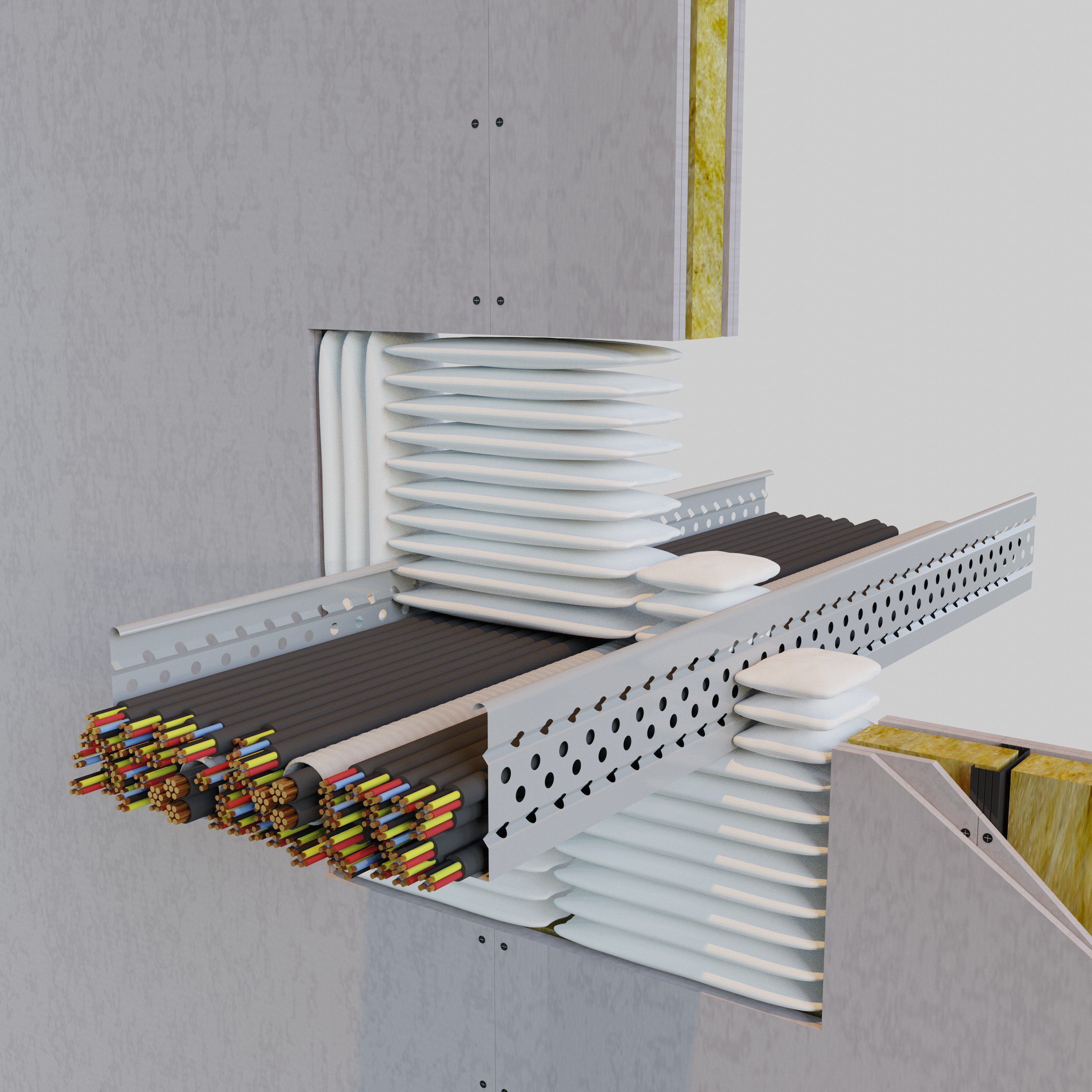 Figure 4a | Sealing depth 120 mm
The first system, our "base case", uses certified
AF Bags with the "short" side of 120 mm
arranged parallel to the structure's thickness;
the longer side of 300 mm is available to
occlude the penetration section. The number
of units required to seal the opening is
optimised accordingly. Since it has not been
used in testing, it is not necessary to provide
an external frame to validate the installation
based on the certification.
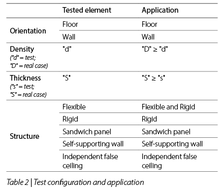
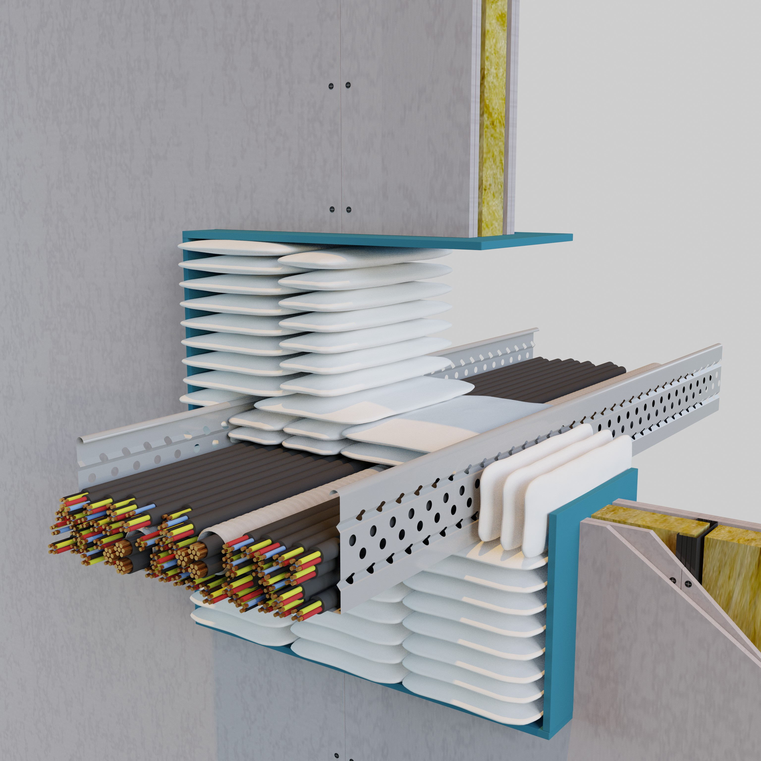 Figure 4b | Sealing depth 320 mm
The second system is certified with pillows
using their 320 mm "long" side arranged
parallel to the structure's thickness and
the 200 mm "short" side to occlude the
penetration section. The number of pillows
required for sealing is approx. 65-70% higher
than in our base case. It is necessary to add a
250 mm deep frame for a certified installation.
 Figure 4c | Sealing depth 600 mm
The system is certified as in the second case
with the "long" side of 300 mm arranged
parallel to the structure's thickness and
the addition of pillows on both sides of the
penetration for an additional 150 mm sealing
depth on each side of the cable trays. The
combination of these two factors greatly
increases the number of units required to
achieve a compliant seal, leading to more
than double the pillows used in the base
case. Addition of a frame required.
 Figure 5 | Air duct test schemes under EN 1366-1
Other differences between ducts can be found in their geometry and orientation. Horizontal (ho) and vertical (ve) penetration duct tests must be performed, and circular and rectangular cross-section ducts used in the test. The standard does not allow the product to be applied in configurations that have not been tested and it is not possible to certify a circular cross-section duct with a test performed on a rectangular cross-section duct.
Fire dampers (EN 1366-2)
An alternative for air duct penetration protection is inserting fireproof elements inside the walls/floors delimiting the compartments, which decouples the section of duct in one compartment and the one adjacent.
The reference standard, EN 1366-2 tests these
fire dampers
.
For these systems, there is a product standard and CE marking obligations. The mechanism interrupts the duct at the fire resistant partition using a silicate (or equivalent material) blade. Fire dampers are only used when the flow of air can be blocked if there is a fire. The standard describes the installation criteria. Fire dampers can be installed on masonry or flexible walls following the procedures outlined for each configuration, and the damper must not be installed on an untested structure. The perimeter around the damper must be sealed using the methods indicated in the product data sheet.
If it is going to be used outside the supporting construction (offset), this must be tested.
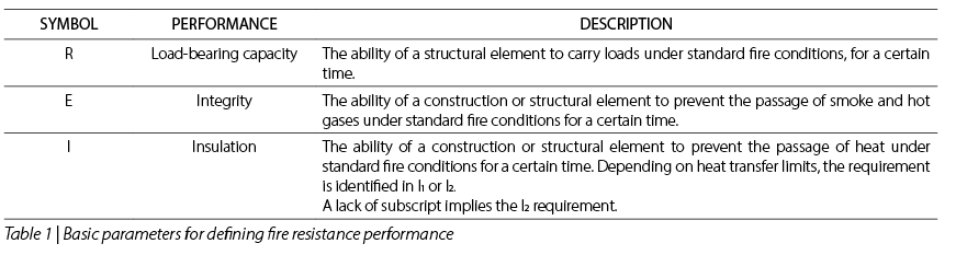
The penetrations of
electrical cables
is one of the most
critical points
for the compartmentalisation of buildings due to the high risk of fire. Short circuits and current overloads, faults in the conductors or connection terminals can generate strong overheating and wear or "ignite" the cable insulation layers.
EN 1366-3 certified systems upgrade the penetration by protecting the free space around the cables and ensure that flames and combustion gases do not pass from one compartment to another if there is a fire.
Due to its high criticality, the electrical cable penetration must always be made safe and even for small penetrations, there is no European legislation that allows exceptions*.
At the regulatory level, cables can be distinguished by function in electricity or telecommunications, by small, medium and large sizes and the insulating jacket. In civil construction, most cases are concentrated on small sheathed cables (outer diameter less than or equal to 21 mm). It is important to check that the cable diameter is within the tested ranges and achieves the required fire resistance.
In most installation configurations, cables are housed inside non-combustible metal cable trays but can be placed inside plastic pipes (usually corrugated PVC pipes) or, in extreme cases, remain free without any external support system.
The sealing systems, have a great variety and flexibility depending on the need for maintenance or the implementation of design variations (e.g. insertion of other cables). The most flexible solutions include intumescent pillows and bricks, which can be easily removed and relocated. Intermediate or semi-rigid solutions include low density panels or two component intumescent foams that can be easily perforated, and "rigid" solutions include sealing the opening with cement mortars. Maintenance or variation requirements of the electrical system make rigid systems rare and most of the fireproof sealing systems recently put on the market (e.g. fire bricks) are easily removable to facilitate maintenance on the network.
In addition to the flexibility requirements, the sealing depth is the main differentiating parameter of cable penetration sealing systems from the user's point of view. The different solutions available on the market start from
120 mm
(e.g. AF Bags and AF Masa in this catalogue) up to more than
300 mm
.
A smaller depth of certified sealing is preferable for design and application reasons, as it decreases the risk of the insulation thickness exceeding the structure thickness and the overall costs.
*
In some countries, national regulations or the electrical code exclude the need for protection for small penetrations. One example is IEC 20-36/4-0 which describes the test methods for the fire resistance of certain cables but does not mention the penetration test standard.
The standard divides pipes into two macro groups: combustible and non-combustible.
Here are some aspects that differentiate the two groups, starting from the diameter and conditions of the pipe end. For non-combustible pipes to have a valid field of application, the standard requires the minimum diameter (with the lesser thickness) and the maximum diameters (one with the lesser thickness and one with the greater thickness) to be tested; the result obtained is a
range of diameters and thicknesses
.
In Figure 6, all pipes in the dashed area can be protected. A 200 mm diameter pipe and a 8 mm thick wall are within the field of application, while a pipe of the same diameter with a wall thickness of 4 mm is not covered by this certification.
This example shows the correct value of the test carried out in point "C", i.e. on a 40 mm diameter pipe and a 3 mm thick wall thickness. With this test, the manufacturer has extended the scope of its system to smaller pipes with thinner wall thicknesses. This minimum thickness is not automatically extended to all diameters, but only those that fall within the range above.
Figure 6 | Example of cover diagram
The above issue is based on a necessary supposition, namely that the protective systems tested for points "A", "B" and "C" are similar. For collars, it is necessary that the intumescent part and metal structure's thickness, height and consistency are the same for all the points tested.
For the sake of completeness, here is the coverage graph in the EN 1366-3 standard for insulated pipes. This case is more complex because, to achieve an adequate field of application, in addition to the double thickness of the pipe walls, pipes with insulation of different thickness for the same diameters must be tested.
Figure 7 | Cover diagram for insulated pipes
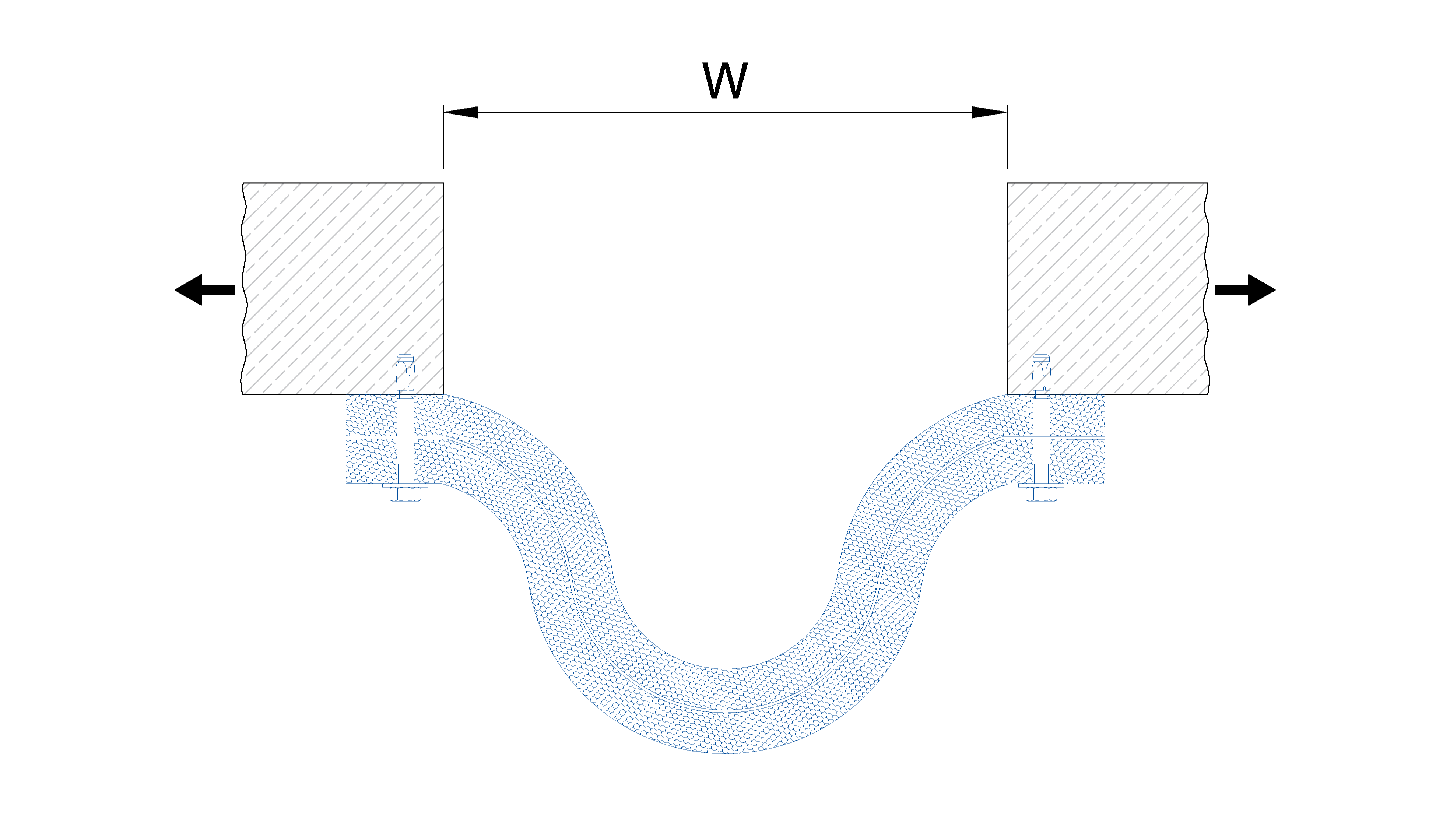
The various configurations correspond to different types of services and the standard refers to them in a special table (see Table 4).
The pipes materials affect the choice of protective system.
Combustible pipes (EN 1366-3)
This type of service loses consistency in the relatively low temperature range of 80-220°C. In a few minutes, the collapsing pipe creates an opening in the structure exposed to the infiltration of flames, smoke and combustion gases. The primary task of a fire-wall is to promptly restore structural integrity by closing any openings generated by the destruction of combustible elements. The most commonly used system employs the chemical reaction known as "intumescence", i.e. the ability of a material, contained in the sealant, to increase its volume as the temperature increases.
This process is generally triggered at temperatures around 180°C and continues until a temperature of about 400°C.
The technopolymer knowledge is important because each type (PVC, PP, HDPE...) melts and behaves differently during a fire. The test standard takes this into account and requires dedicated tests for the different types. It requires testing the sealant's behaviour on composite pipes from different manufacturers.
Unlike the previous type, most "non-combustible" materials (e.g. iron, steel and copper) melt at a temperature above 1000°C and maintain their integrity during a fire. High conductivity causes materials to quickly overheat and become a source of fire ignition in other compartments. The thermal insulation work keeps the penetration unexposed by covering it with insulating protective or ablative coatings.
Aluminium may not remain intact during a fire since it melts at relatively low temperatures (about 600°C). This significant difference in fire behaviour makes metals melting at temperatures below 1000 °C critical and where insulating materials are not sufficient to guarantee temperatures below their melting point, the system must use intumescent materials capable of restoring the substrate integrity.
Where metal pipes are insulated, the nature of the insulation must be taken into account. If the insulation is combustible, the pipe is protected with a thermo-expansive product, such as a collar or intumescent strip.
Depending on the method certified by the manufacturer, the sealing system can be applied directly to the coating or after removal and replacement of the insulation. All certified systems do not require replacing the insulation (e.g. the collar is applied directly onto the elastomeric insulation). If the lining cupel is made of non-combustible mineral wool (class A1 or A2) with melting temperatures higher than those in the test furnace, the insulation shrinks but does not disappear. It is important to ensure the sealing integrity along the contact perimeter between the mineral wool and the structure. This can be carried out using intumescent elements or other types of sealants such as acrylics. The standard specifies that test results from glass wool cupels with relatively low melting temperatures can be extended to stone wool cupels; but not vice versa.
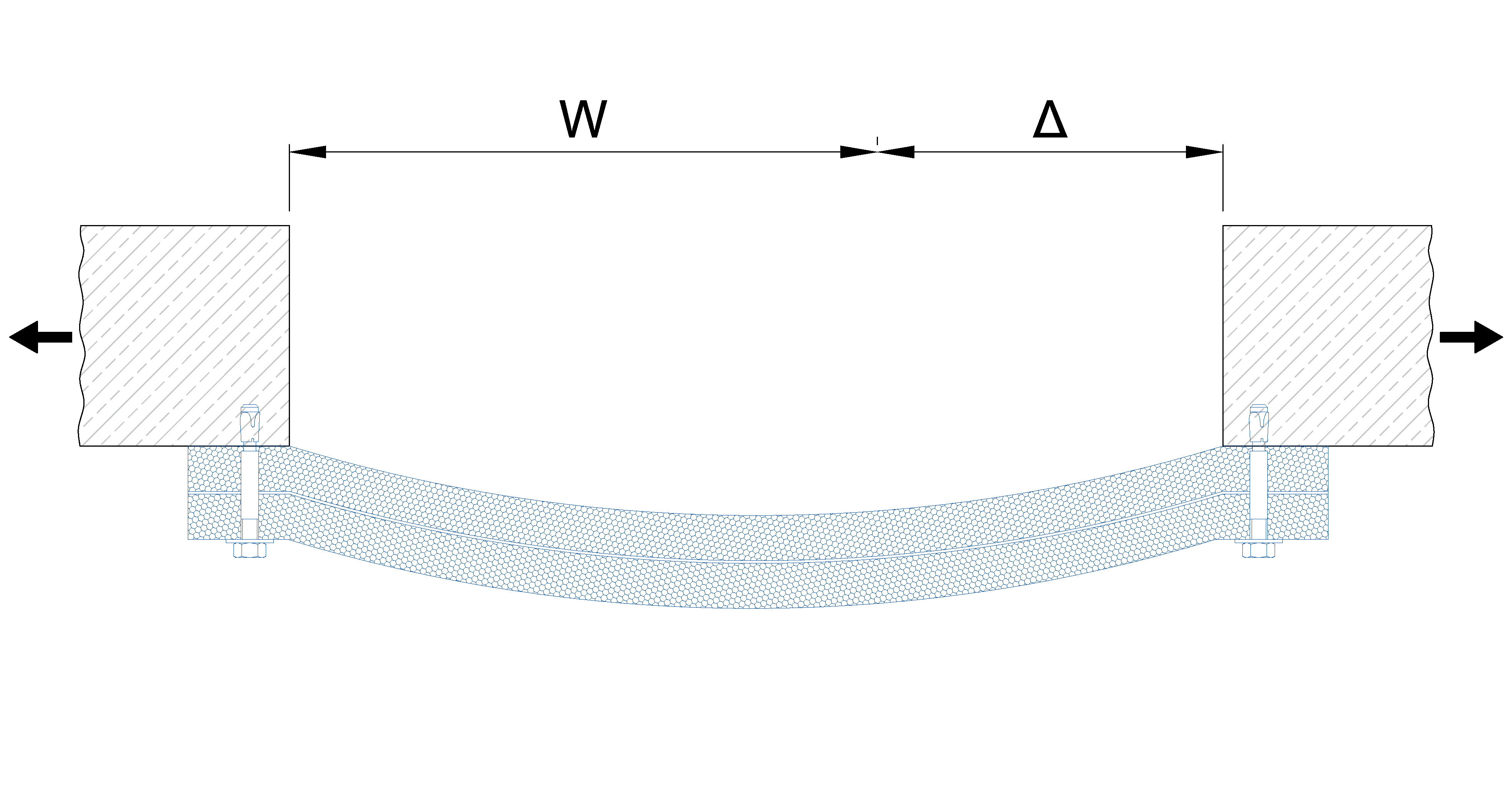
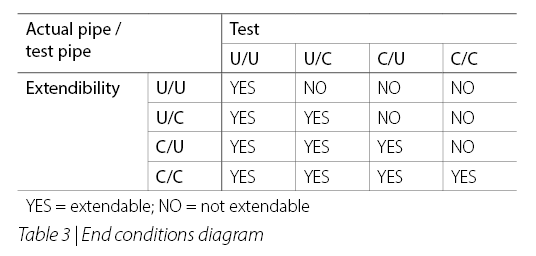
after extension movement "Δ"
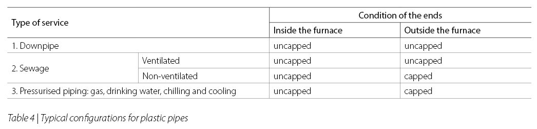
Linear joints are defined as a seam in a wall or floor that has a length to width ratio of at least 10:1. The inclusion of these openings in the design phase responds in most cases to a need for structural flexibility. These open spaces are buffers that prevent small structural movements (due, for example, to thermal expansion or ground vibrations) from causing cracks or breaks in the materials. The linear joint is an element of tension between the need for mechanical stability and fire compartmentalisation.
For this reason passive fire protection is preferred for systems that are not completely rigid, which can allow a certain degree of structural movement.
The standard distinguishes between two cases: joints without movement, which can be sealed due to the need for compartmentalisation with protections that can compress and expand up to 7.5% of the nominal width of the joint, and joints with movement that can be sealed with systems that can compress and expand more than 7.5%.
In the first case, the test standard (EN 1366-4) does not require a movement test, while in the second case, after properly sealing the cavity (and before the start of the test) the two parts of the supporting structure are brought closer and further apart, to check the integrity and insulation of the joint cover during a mechanical stress.
In countries with frequent seismic activity (Italy is an example) the structural movements related to normal earthquake activity, lead to systems that allow the ends of the joints to move freely. However, there is no need for constant seismic activity to favour motion-tested solutions, and such preference should be given to situations with large temperature variations throughout the year, or constant ground vibrations due to rail vehicles above and below the road surface.
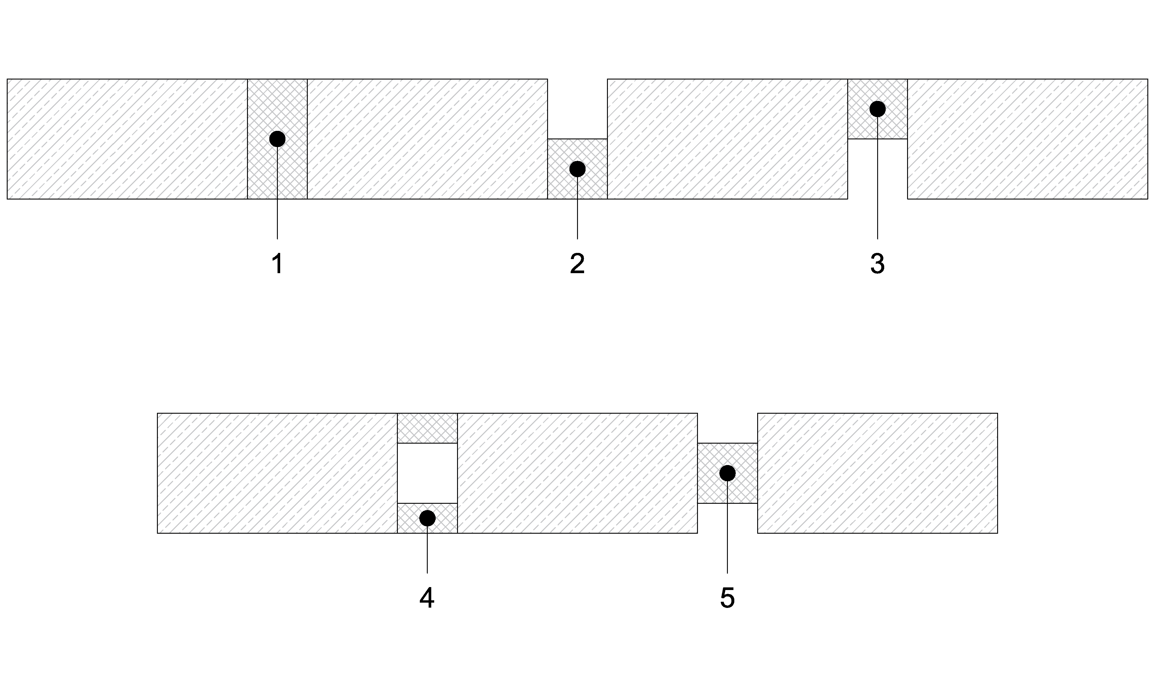
Regardless of the movement condition to which the joint cover was subjected during testing, another important variable is the mounting system of the joint cover. Seals may be placed at different "heights" within the cavity and the test configuration may not necessarily be replicable on site.
The standard requires test conditions to be unchanged. The only exception is the most severe test configuration: if the sealant has been certified for the part exposed to fire (2), it can be applied when the sealant is further away from the fire (3) or (5).
Regulatory framework for product certification
Between 2007 and 2013, the approval of a series of important EU directives in member states extended common criteria for the evaluation of fire resistance products. Since then, the individual member states have maintained their own definition of fire-fighting strategies, but identifying products has been standardised at European level, and today must be assessed based on similar criteria common to all member states.
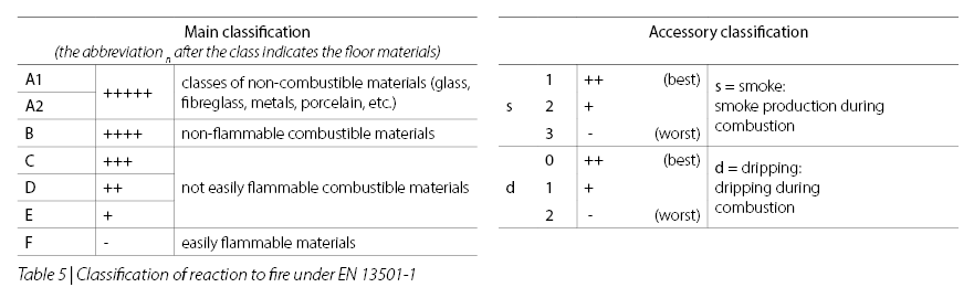
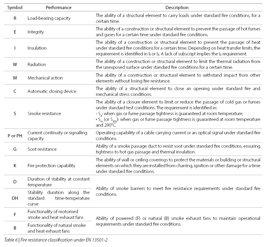
In 2007 there was the mandatory introduction of the two European classifications EN 13501-1 and EN 13501-2, which defined the fire reaction and resistance classes applicable to construction products.
These classifications, which are necessary to compare different products, are shown below (see Table 5 and Table 6).
Classification and test reports
The European fire reaction and resistance classifications use
three different methods:
- the experimental method;
- the analytical method;
- the table comparison.
The three approaches are not perfect substitutes: the fire safety professional can choose the most appropriate method from those available, but not all three can be implemented. We investigate the first of the three approaches, which is often the most onerous and the only one available for evaluating installation penetrations.
The complexity of this method is related to the need to reproduce all critical variables that may affect the behaviour of a protective system in an actual situation during the test phase. For this reason, in addition to the fire temperatures of ISO 834, an overpressure of 20 Pa on average is applied in the test furnaces. This tends to push flames and fumes outwards, making it more difficult to pass the test. For elements with a structural function, it is necessary to apply weights to evaluate their structural stability under fire conditions.
To meet European standards, the tests must be performed in a laboratory accredited by the country's ministerial authorities and "Accredia", a supranational body that certifies the minimum requirements of official laboratories. The detailed description of systems' test results and strength classification are found in two different documents:
(a) Test Report (confidential document)
This document contains all data relating to the sample submitted for testing. This is a detailed document, which includes the verbal description of the samples, drawings and diagrams illustrating the fastening systems and distances between the various tested elements;
b) Classification Report (public document)
This document shows the official classification for each tested item according to test results.
Let us look at some classifications taken from real reports which use concepts from the previous paragraphs.
Table 7 shows four different classification examples selected from actual reports. The descriptions are abbreviated due to space requirements and for introduction purposes, each element is detailed in the report.
Each test is unambiguously associated with a specific standard (e.g. it is not possible to test joint and pipe sealing systems in a single session) and with a specific orientation of the test structure: "vertical" if the sample is a wall and "horizontal" if the sample is a floor. Under these conditions, i.e. with the same standard and orientation, it is possible to test different solutions. This can be seen by comparing the second and third rows of the table, which show a solution with a collar and another with special applications on the panel: a combustible cable tray and a busbar within the same floor.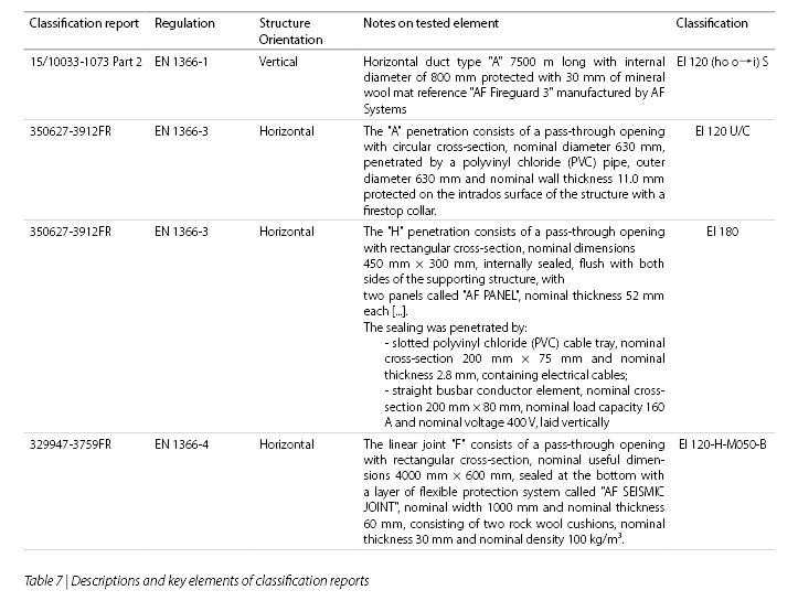
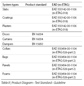
The entry into force of CPR No. 305 of 2011, has made the CE marking for all building materials for which there is a harmonised product standard mandatory across Europe as of 2013, with some exceptions. Within the world of passive protection, there is no product standard for a wide range of systems but only a test standar (e.g. EN 1366-3) for which there is no mandatory requirement. The following diagram (Table 8) gives an updated picture as of this guide's date of publication. There is a product standard for doors, curtains and dampers.
For this reason, their production and marketing is subject to CE marking. The rest of the most commonly used structural protection and sealing products do not have a harmonised product standard and the fire resistance tests organised in official laboratories are sufficient to guarantee their validity and potential applicability.
Even without any product obligation, it is possible to request a CE marking, passing through an intermediate step: obtaining a European Technical Assessment (more commonly abbreviated by the acronym ETA) following the guidelines (ETAG or EAD) for each type of product2.
ETA is a document that collects the results of the tests performed on the same system by accredited laboratories. The ETA of a product range called "AF Bags" groups all relevant installation methods and performance that can be found in the various test and classification reports for that sealing system in a single document.
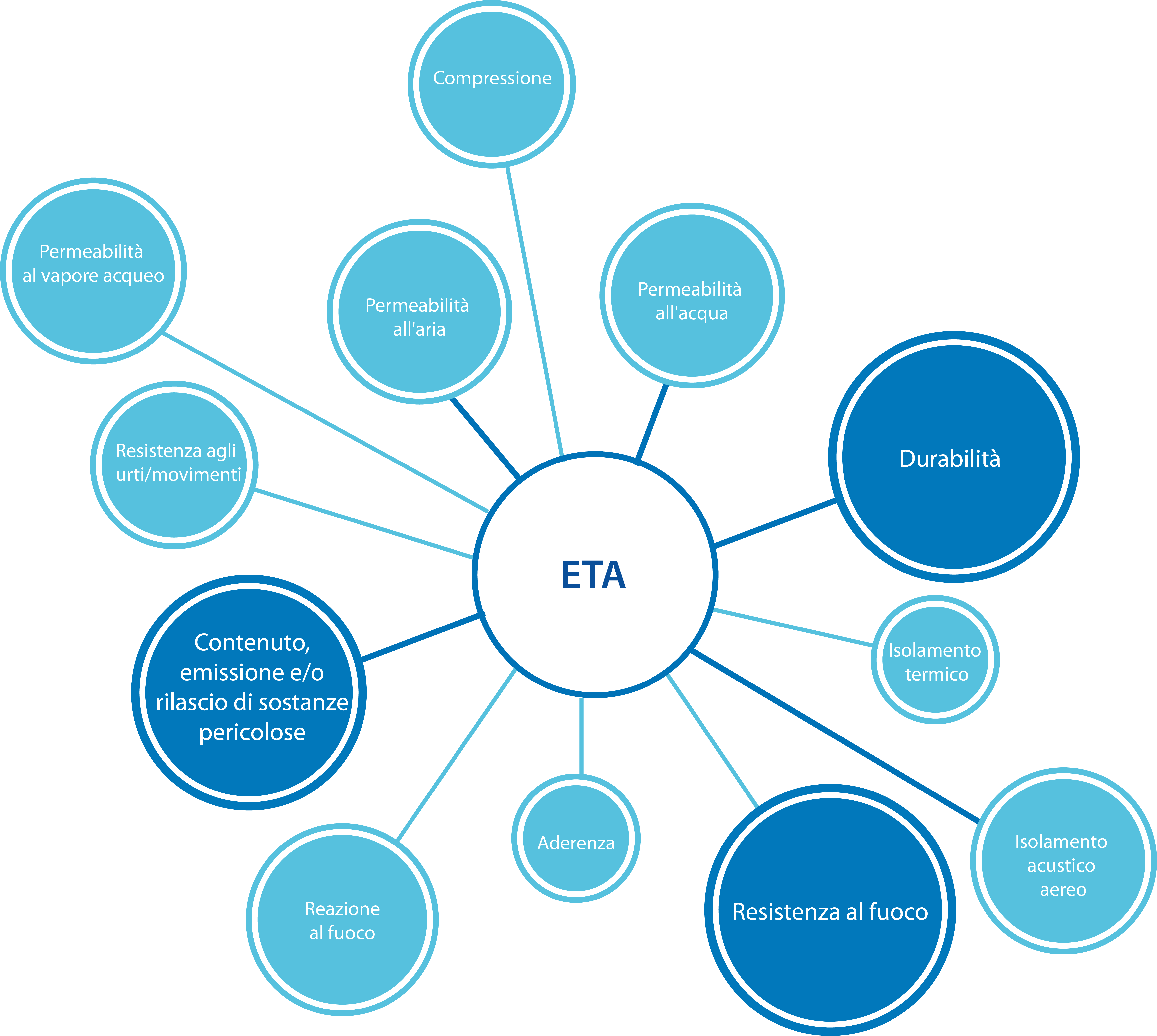
The test results in an ETA do not just cover fire resistance features,
but a range of other results that the manufacturer considers useful to qualify product performance. A list of all variables that can be included in an ETA for fire sealants, extracted from EAD 350454-00-1106 (ex ETAG 026 - Part 2) is available in the following chart.
The inclusion of results related to additional functions for which a system is certified is at the discretion of the manufacturer with the exception of two mandatory parameters: the system's chemical-physical characterisation and durability.
The first of these two characterisations guarantees the absence of toxic substances in the material and that the products maintain the same composition over time. This is an essential element for qualifying the products to be suitable for the CE marking.
The second mandatory characterisation is durability, which verifies the conditions of use for the product or system to maintain its behaviour unaltered over time. The products that make up the sealing system are subjected to accelerated ageing cycles that simulate the impact caused to the system by certain environmental conditions over a prolonged period of several weeks (or months). The standard time considered to validate a system is normally 10 years, but it is possible to simulate a longer time by extending the ageing cycles of these products.
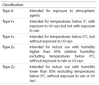
Products under type Y1, include classes Y2, Z1 and Z2.
Products under type Y2 meet the Z1 and Z2requirements.
Products under type Z1, meet type Z2 requirements.
The durability classification is important. If direct exposure to ultraviolet rays and rain is relatively negligible for compartmentalisation products, which are mostly intended for indoor use and without direct exposure to atmospheric agents, exposure to high humidity and temperatures that drop below 0°C in winter is common, and a class characterisation higher than "Z" is recommended. AF Systems chooses to use stainless steel for the structure of its collars and treatments that are not affected by humidity or temperature changes for this reason.
Once fire resistance, mandatory chemical-physical characterisation, durability and other performance tests have been carried out, the ETA drafting by one of the Technical Assessment Bodies (TAB) appointed by the governments of each Union Member State begins. In addition to collecting the results of the same certified system, the TAB may request additional tests from the manufacturer and add technical evaluations which extend the individual certificate's scope. The ETA issued as a temporary version by a TAB must circulate for a certain time within the EOTA, which is the association of European TABs, and monitors the ETA process. If during this time no objections are raised, or objections are remedied through additional testing/submission of ancillary documentation, the ETA can be issued.
However, obtaining an ETA and issuing a DoP is not sufficient to ensure that a CE marking is obtained. This requires proof of performance consistency, i.e. that the samples used in the test conform to those of current production and the production process is consistent.
To achieve these ambitious goals it is necessary to implement a factory production control system, constantly verified through audits carried out by professionals appointed by the relevant TAB. Since passive fire protection falls under the most stringent European Union controls (type 1/1+ of the "Assessment and Verification of Constancy of Performance (AVCP)" system), it is necessary to carry out at least two audits every year for each product subject to CE marking with the possibility of withdrawing any marking already issued if there are serious production non-conformities.
This makes it possible to understand why if the ETA has an indefinite duration, the CE marking has a time span of one year, and every twelve months the performance consistency certificates must be renewed.
The above operational difficulties have led many companies that have separate commercial and production organisations (e.g. with outsourced or delocalised manufacturing) to set the achievement of an ETA and not CE marking as their final objective.
AF Systems is proud to be the first, and possibly the only Italian company to have obtained ETA and voluntary CE marking for its products for the sealing of pipe penetrations (AF Fireguard 3), pipes and cables (AF Collar, AF Multicollar, AF Collar C, AF Sleeve and AF Bags) and fire protection of expansion joints (AF Joint and AF Seismic Joint). The process of converting test and classification reports to ETA and CE marking is underway on other products in our catalogue to guarantee our customers that they can always count on solutions that reach the highest levels of innovation and reliability.
From design to certified installation:
a single Partner for passive fire protection with an eye always towards innovation.

MENU
USEFUL LINKS
Contact
Via Jenner, 41/43
Mulazzano (LO) - 26837
Tel. +39 0298879353
Registered Office:
Via San Siro, 38
Piacenza (PC) - 29121
Contact us